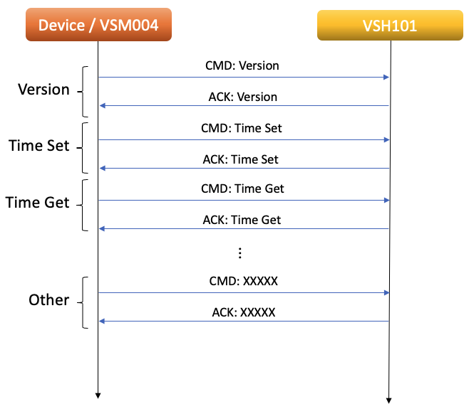
After establishing a connection with VSH101, the initial communication flow is as follows:
If the ”VSC MODE“ or “VSC_FILE_MODE” instructions have not been executed, it is necessary to transmit instructions every 10 seconds to maintain the connection.
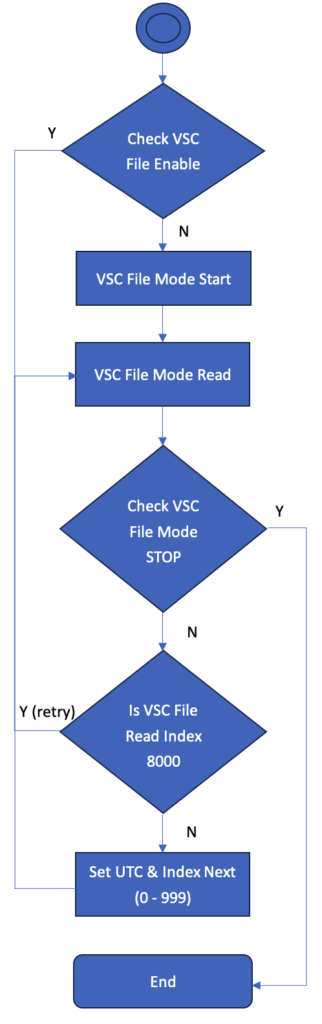
VSH101 VSC FILE MODE Flow Chart
This functionality requires a firmware update to version 223.
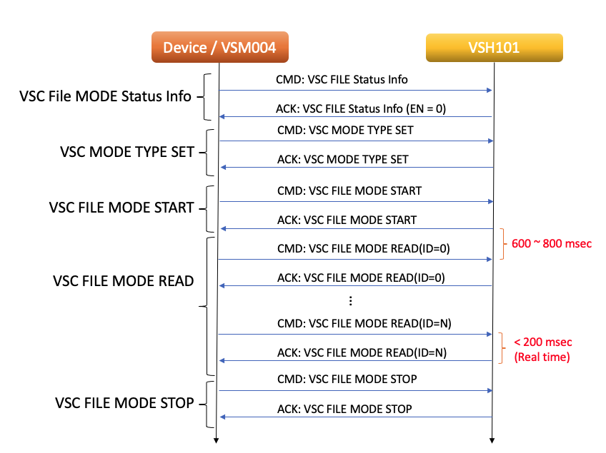
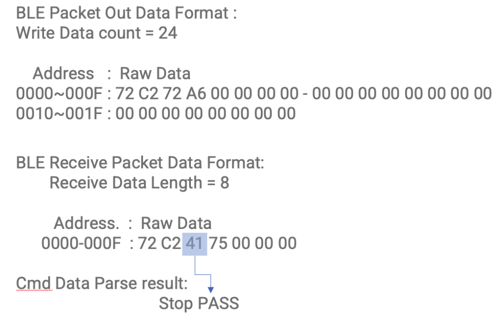
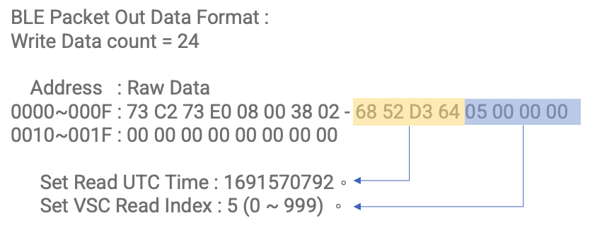
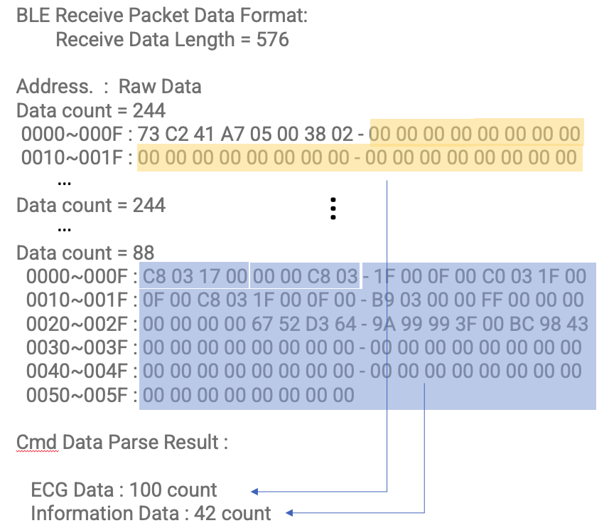
The VSC FILE MODE START and VSC FILE MODE STOP commands are straightforward, similar to the other BLE commands discussed earlier. However, the VSC FILE MODE READ command is slightly more intricate. When a user initiates the VSC FILE MODE READ command, the device will respond with 968/576 bytes of data. The subsequent section will provide a more detailed explanation of the VSC Mode Data Format.
For real-time information, each VSC FILE MODE READ command contains 100 ms of ECG data along with pertinent information.
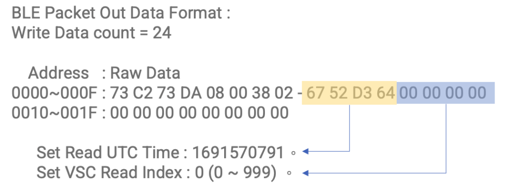
Upon establishing the connection, the first step is to read the VSC File Status Information to confirm whether the VSC FILE MODE is currently active. If it is active, you have the option to choose between starting from the last read data or directly accessing the latest data for retrieval.
Each individual data is generated every 200 milliseconds. Therefore, after every 5 packets following the VSC FILE MODE START command, the UTC value should be incremented by 1.
When the APP uses VSC MODE FILE READ for real-time ECG data and related information, the communication transmission interval should be less than 200 milliseconds.
Hour
Min
Sec
Delta Time
Delta Send
Event
15
24
37.724
[Cmd]VscFileRead Send
15
24
37.867
0.143
Receive BLE_VSC_FILE_READ ID = 1
15
24
37.877
0.01
0.153
[Cmd]VscFileRead Send
15
24
38.023
0.146
Receive BLE_VSC_FILE_READ ID = 2
15
24
38.05
0.027
0.173
[Cmd]VscFileRead Send
15
24
38.228
0.178
Receive BLE_VSC_FILE_READ ID = 3
15
24
38.246
0.018
0.196
[Cmd]VscFileRead Send
15
24
38.41
0.164
Receive BLE_VSC_FILE_READ ID = 4
15
24
38.418
0.008
0.172
[Cmd]VscFileRead Send
15
24
38.600
0.182
Receive BLE_VSC_FILE_READ ID = 5
VSH101 BLE Profile :
Service profile: 6e400001-b5a3-f393-e0a9-e50e24dcca9e
Each individual data is generated every 200 milliseconds. The reading interval for the data can be configured to be between 100 to 200 milliseconds.
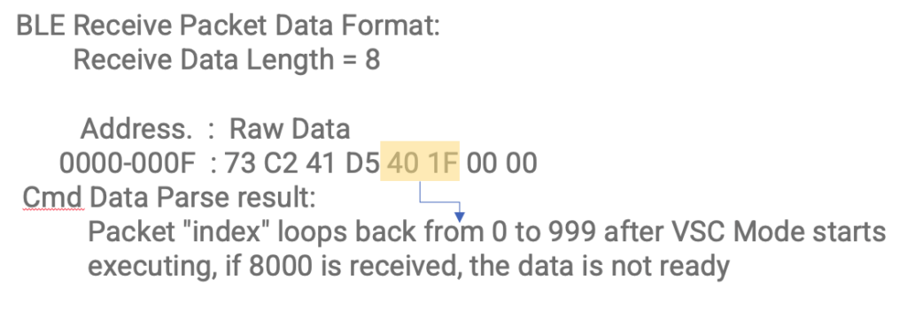
Once the packet index reaches 8000, a 100-millisecond delay is introduced before attempting another read. If the subsequent read is successful, the process would resemble the below:
Each individual data is generated every 200 milliseconds.and the data from to the next second is as follows:
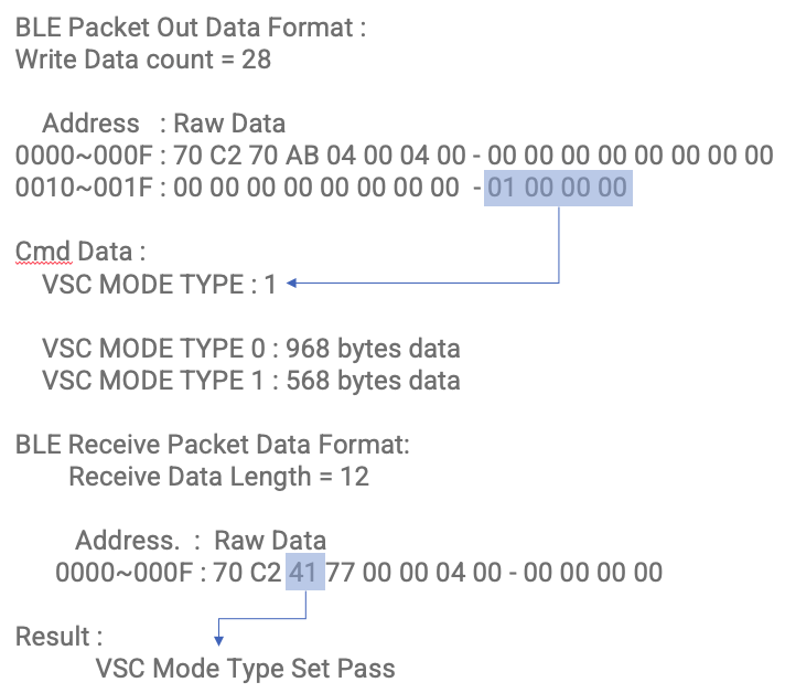
VSC MODE TYPE 1 Data Format
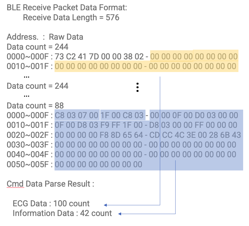
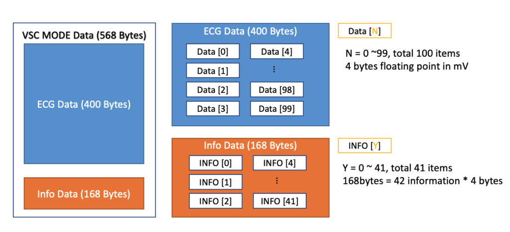
As mentioned, There are 568 bytees of returning data of VSC MODE READ. It includes two parts:
ECG DATA (400 bytes) – 1 channel ECG datas
INFO DATA (168 bytes) – 42 information
The detail description is listed below:
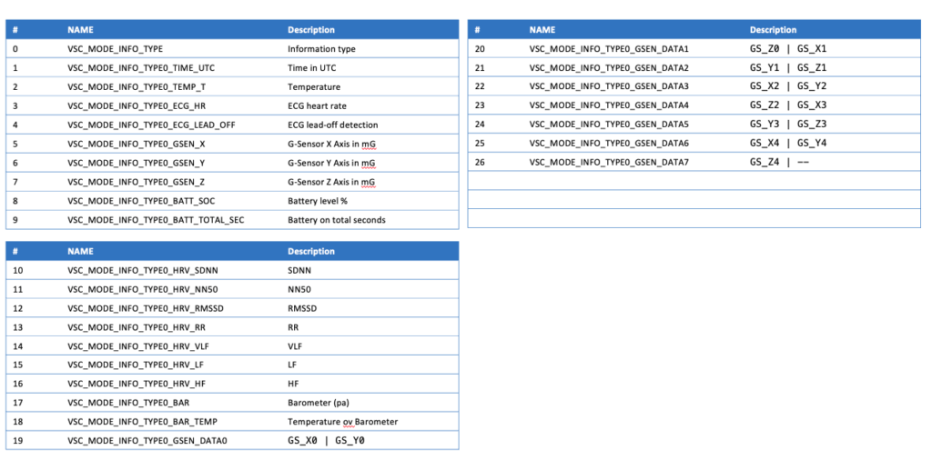
The INFO Data included 26 information for user to do the monitoring. It is listed below:
It includes Time (1), temperature(2), ECG data(2, 3), G-Sensor (5, 6, 7), Battery Status (8, 9), HRV (10, 11, 12, 13, 14, 15, 16), Barometer values(17, 18), and 5 G-Sensor points during the period (GS_X0..5, GS_Y0..5, GS_Z0..5).
Since the G-Sensor inside will keep monitor patient’s activity in a sampling rate of 25 Hz. A VSC Mode Data includes 200 ms information and it means the VSC Mode Data will have 5 points of G-Sensor data and they are GS_X0..5, GS_Y0..5, GS_Z0..5.
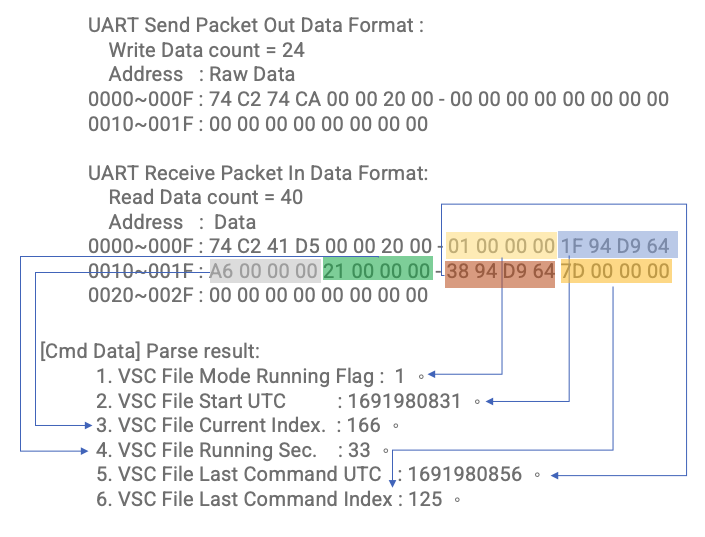
8. VSC File Status information Packet Command
Name
Hex Data
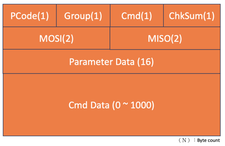
PCode
0x74
Group Id
0xC2
Cmd
0x74
Check sum
0xCA
MOSI
0x0000
MISO
0x0020
Parameter Data
00 00 00 00 00 00 00 00 00 00 00 00 00 00 00 00
Cmd Data
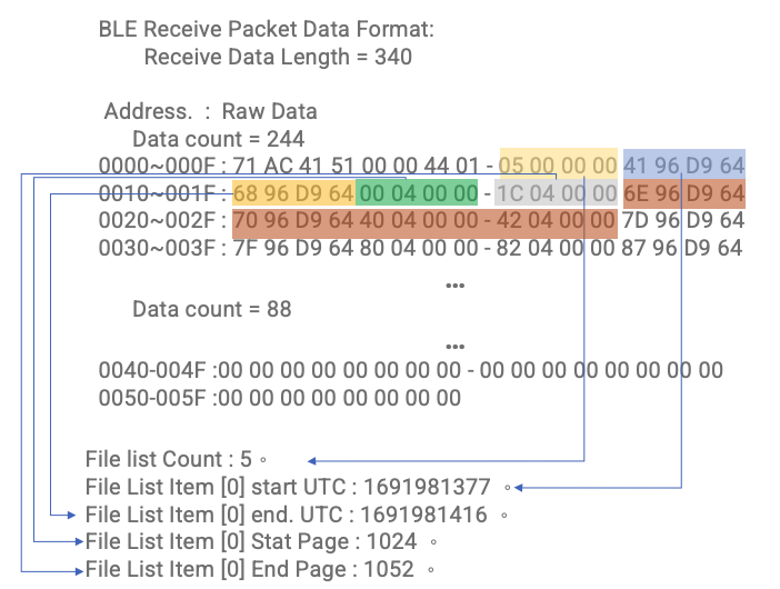
9. File List Get Packet Command
Name
Hex Data
PCode
0x71
Group Id
0xAC
Cmd
0x71
Check sum
0xDA
MOSI
0x0000
MISO
0x0144
Parameter Data
00 00 00 00 00 00 00 00 00 00 00 00 00 00 00 00
Cmd Data
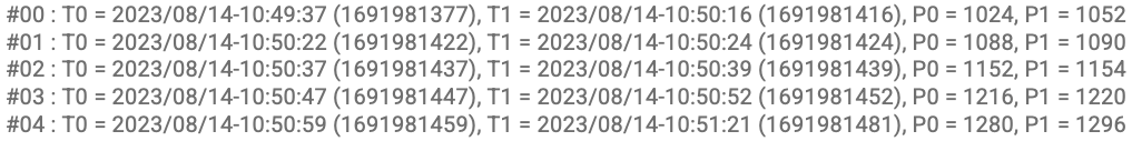
Each item in the file consists of the following information, each occupying 16 bytes:
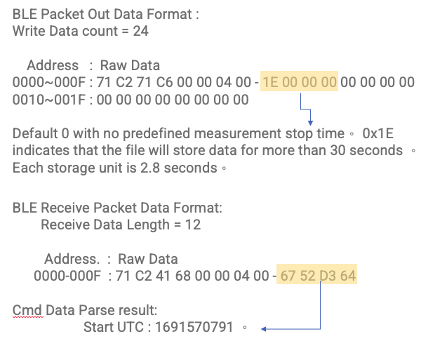
Start UTC (Coordinated Universal Time at the beginning)
End UTC (Coordinated Universal Time at the end)
Start Page (Starting data flash page index)
End Page (Ending data flash page index)
There can be a maximum of 20 items. Additionally, there is a count represented using 4 bytes, indicating the total 324 bytes.
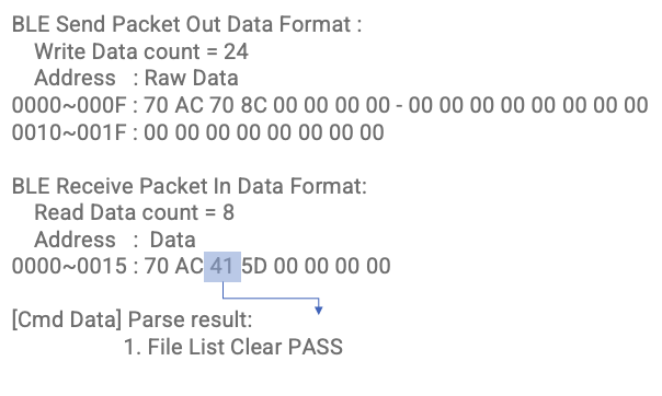
10. File List Clear Packet Command
Name
Hex Data
PCode
0x70
Group Id
0xC2
Cmd
0x70
Check sum
0x8C
MOSI
0x0000
MISO
0x0000
Parameter Data
00 00 00 00 00 00 00 00 00 00 00 00 00 00 00 00
Cmd Data
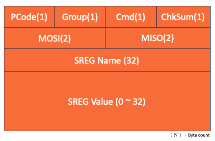
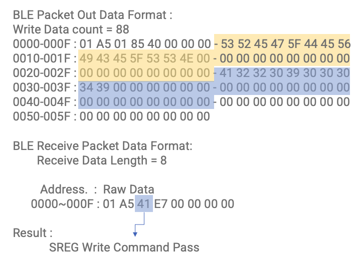
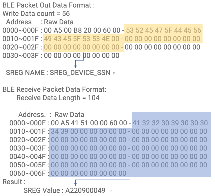
Soft Register Send Packet Format
Soft Register Table
SREG NAME
SREG TYPE
Value Byte Size
Note
SREG_DEVICE_NAME
STRING
20
BLE Device Name
SREG_DEVICE_RESET
0
SREG Write then reset device
SREG_DEVICE_SSN
STRING
32
Device SSN
SREG_MEAS_LEAD_OFF
INT
4
0: Disable, 1: Enable
SREG_DEVICE_ID
INT
4
Device ID
SREG_DEVICE_BEACON
INT
4
0: Disable, 1: Enable
SREG_VSC_MODE_TYPE
INT
4
0: Type 0, 1: Type 1
SREG_CHARG_POWER_DOWN
INT
4
0: Disable, 1: Enable
SREG_ADVERTISING_INTERVAL
INT
4
advertising interval setting range : 20 ~ 1000 (mSec)