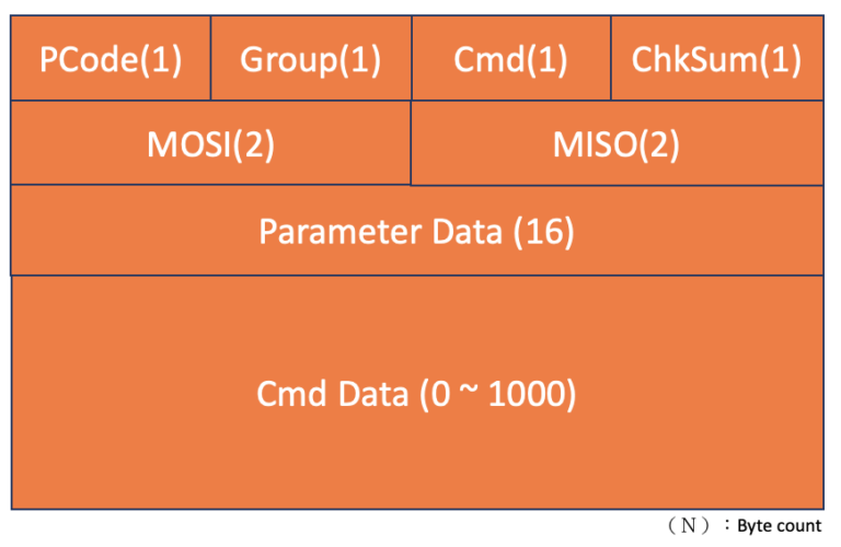
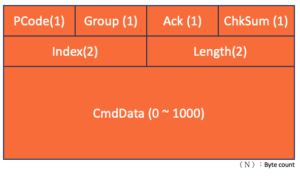
Data Structure and Specifications
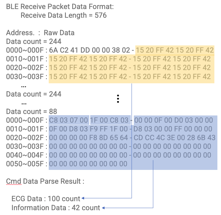
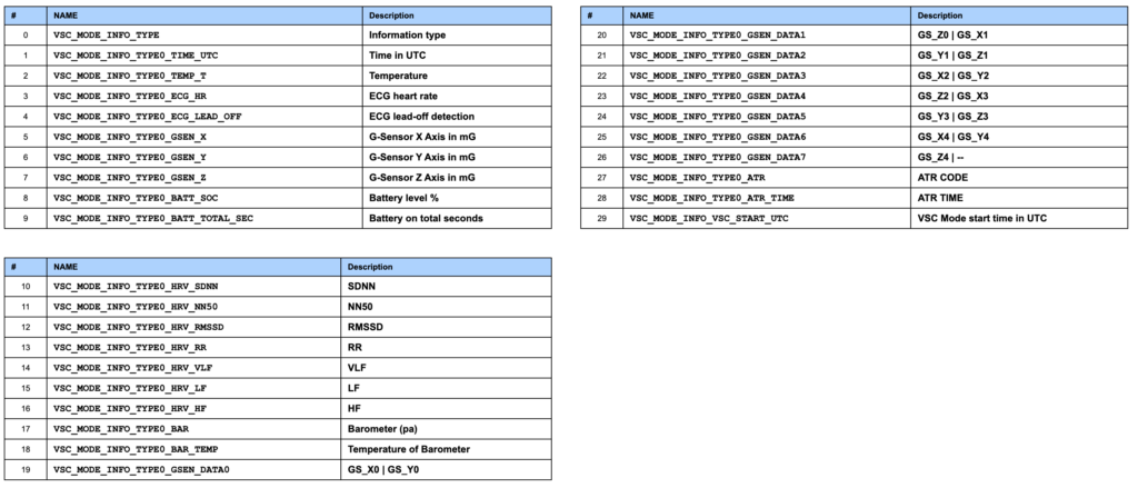
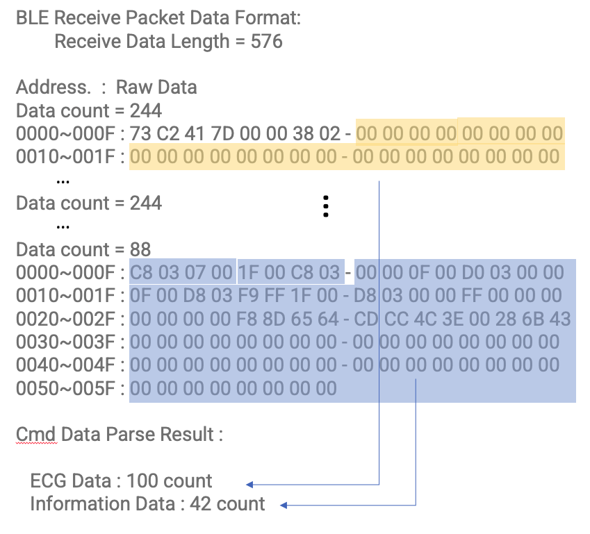
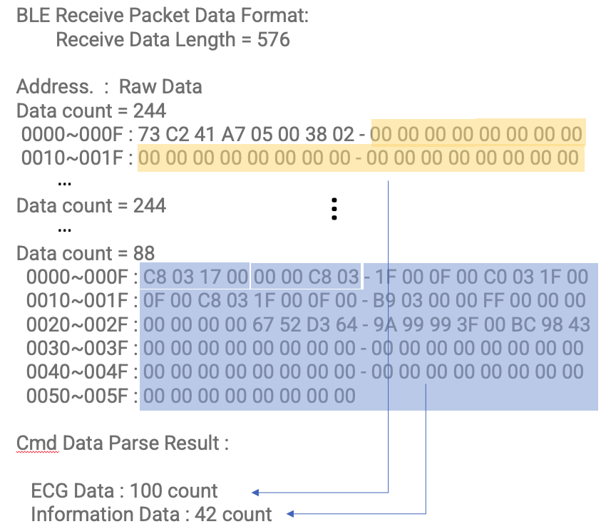
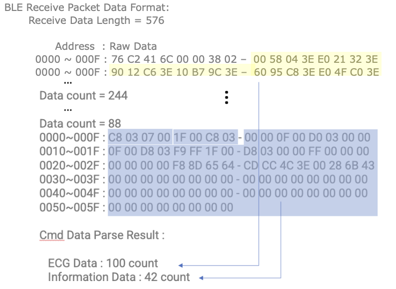
The data packet includes Time (1), Temperature (2), ECG data (3, 4), G-Sensor (5, 6, 7), Battery Status (8, 9), HRV (10–16), Barometer values (17, 18), ATR data (27, 28), and the VSC Mode start time (29). Additionally, it contains five G-Sensor data points captured during the period (GS_X0..4, GS_Y0..4, GS_Z0..4).
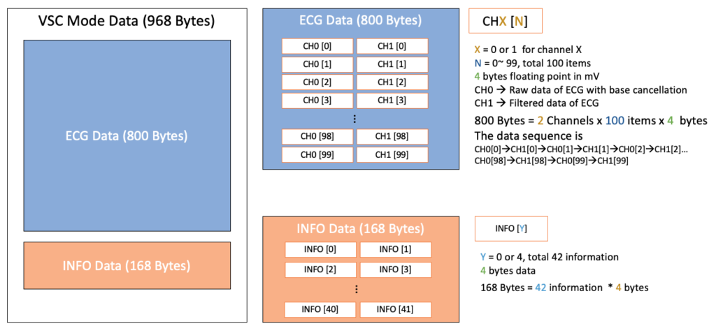
Data Conversion Note: Except for the G-Sensor data points, all values are converted and processed as 4-byte floats.
G-Sensor Monitoring
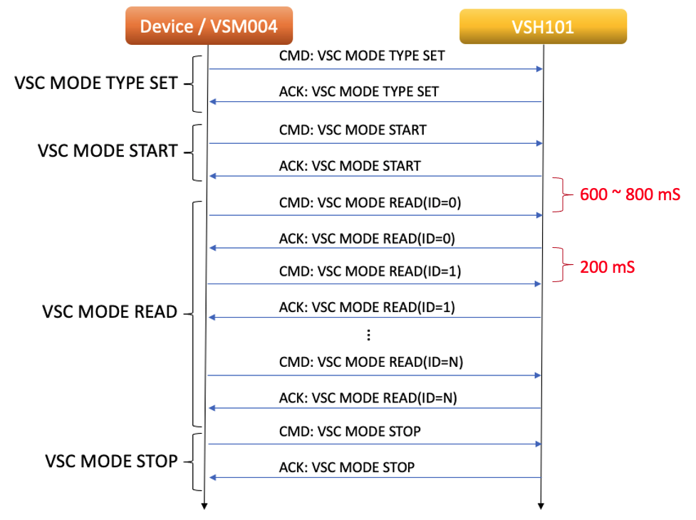
The internal G-Sensor continuously monitors patient activity at a sampling rate of 25 Hz. Each VSC Mode data block covers a 200 ms window, which consistently contains 5 G-Sensor points (GS_X0..4, GS_Y0..4, GS_Z0..4) to align with the sampling frequency.
ATR (Annotation Trigger Record)
The ATR is used to mark specific ECG-related or physiological events. The encoding follows the PhysioNet ECG code definitions (referenced from the PhysioNet Archive), with the following addition:
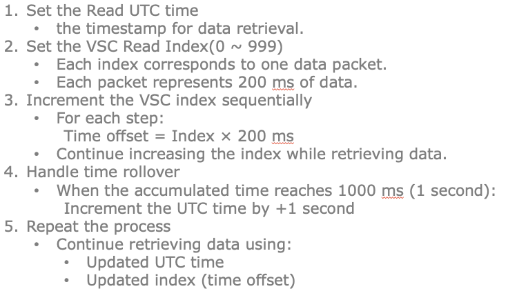
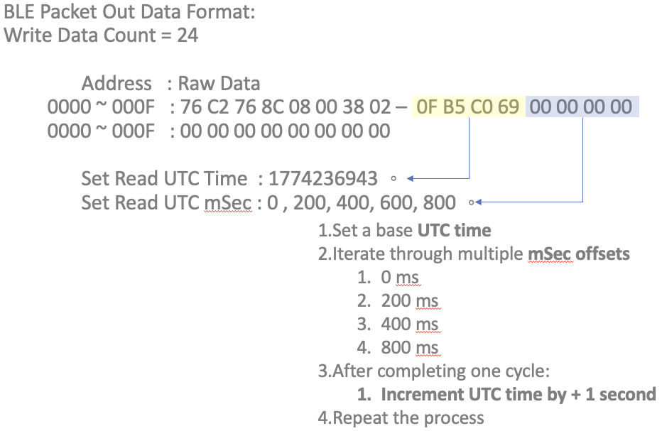
ATR Timestamp Calculation: To ensure precise alignment between the ATR events and the continuous physiological data stream, the actual timestamp is calculated as follows:
ATR Timestamp = VSC_Mode_Start_UTC + (ATR_TIME / 1000)