VitalSigns ECG Cloud Integration Tutorial
JL Juang
2026-02-13
Introduction
Purpose of This Tutorial
This tutorial demonstrates how to build a complete ECG data pipeline using VitalSigns devices and an open-source backend.
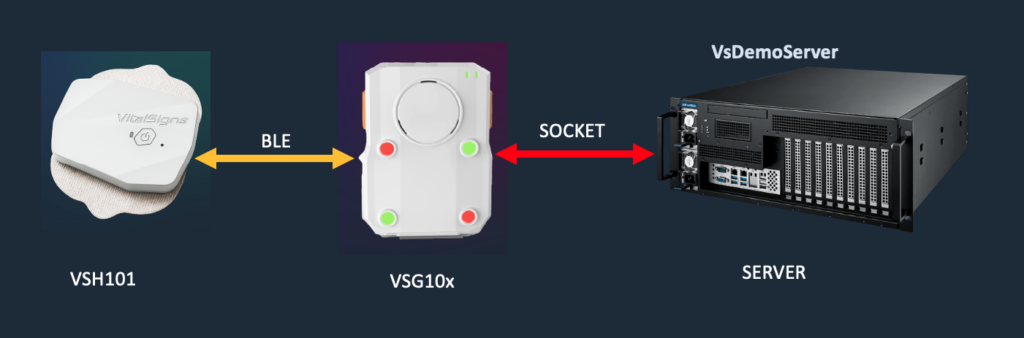
As shown in the diagram:
The VSH101 collects ECG signals from the patient
The VSG10x gateway receives ECG data via BLE (Bluetooth Low Energy)
The gateway then securely transmits data to the backend using a TCP socket connection
The Demo Server (VsDemoServer) receives, processes, and stores the data for further integration
This tutorial focuses on helping engineers understand how to:
Establish end-to-end communication from device to server
Handle encrypted data transmission between gateway and backend
Build a file-based data pipeline for ECG storage
Extend the system into their own database, AI models, and SaaS platforms
By following this guide, developers can quickly transform this reference architecture into a production-ready ECG cloud solution tailored to their own applications.
What to Build
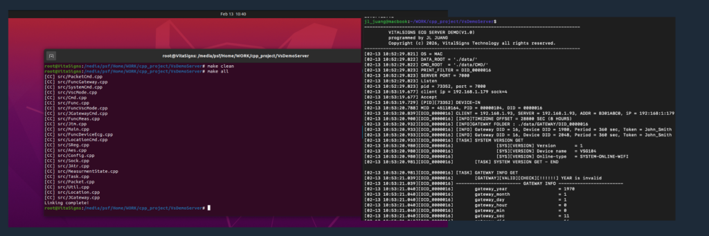
In this tutorial, you will build a working ECG backend service on a Linux (Ubuntu) server using the provided C-based Demo Server.
As shown in the figure below, the system is compiled and built directly from source using standard Linux tools (make), providing full transparency and control for developers.
By completing this guide, you will have:
A C-based backend service running on Ubuntu that communicates with the VSG10x gateway over a TCP socket
A fully functional end-to-end ECG data pipeline, from VSH101 → Gateway → Server
An automated measurement loop (360 seconds measurement / 60 seconds rest)
A secure encrypted communication channel between gateway and server
A file-based data storage system that organizes ECG data by device and session
A backend architecture that can be extended into:
A database system (e.g., MySQL, PostgreSQL, NoSQL)
An AI pipeline (e.g., AF detection, HRV analysis, MI prediction)
A SaaS healthcare platform
Devices Used in This Demo
This tutorial uses the following devices to demonstrate a complete ECG data pipeline:
Gateway
A VSG10x gateway responsible for receiving ECG data via BLE and forwarding it to the backend server over an encrypted TCP connection.ECG Device
A VSH101 single-lead ECG device that captures physiological signals and transmits them to the gateway via Bluetooth Low Energy (BLE).
This setup represents a typical deployment scenario where a wearable ECG device is connected to a nearby gateway, which then securely relays data to a cloud backend.
The same architecture can be extended to support:
Multiple gateways per patient (e.g., home, mobile, facility)
Different gateway models (VSG101 / VSG102 / VSG104)
Scalable multi-device and multi-patient environments
Target Audience
This tutorial is intended for engineers and developers who want to build their own ECG data platforms using VitalSigns devices and the provided demo backend.
It is particularly suitable for:
Backend Engineers
who need to receive, process, and store ECG data from connected medical devicesCloud Architects
who are designing scalable, secure healthcare data infrastructuresAI Engineers / Data Scientists
who plan to develop ECG analytics such as atrial fibrillation (AF), heart rate variability (HRV), or myocardial infarction (MI) detectionSaaS Developers
who aim to build digital health platforms, remote monitoring systems, or subscription-based healthcare servicesSystem Integrators
who want to integrate VitalSigns hardware into existing medical or IoT ecosystems
This guide assumes basic familiarity with:
Linux (Ubuntu) environments
C/C++ development and build systems
Network programming (TCP/IP concepts)
1. System Overview
The VitalSigns ECG system is designed as a modular, end-to-end architecture that enables reliable acquisition, transmission, and processing of physiological data.
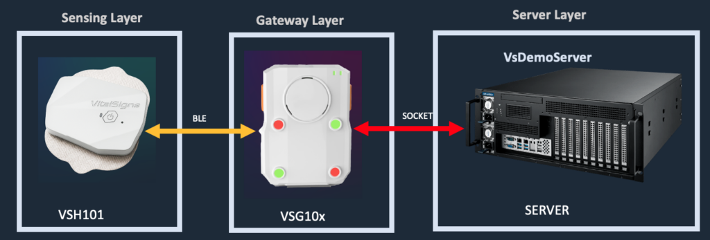
The system separates responsibilities into three layers:
Sensing Layer – ECG signal acquisition from the patient
Gateway Layer – Local aggregation, control, and secure data transmission
Backend Layer – Data reception, storage, and integration into cloud services
This layered architecture allows developers to independently design and scale each component while maintaining a consistent and secure data pipeline.
1.1 Hardware Architecture
The hardware architecture consists of two primary components:
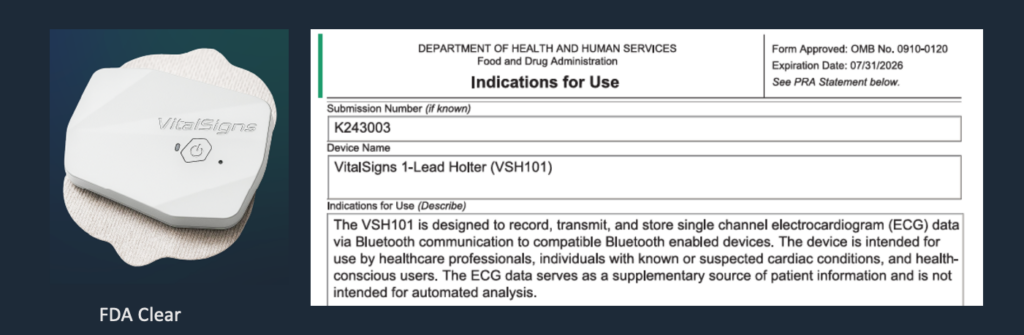
1.1.1 VSH101 – ECG Sensing Device
The VSH101 is a single-lead ECG device responsible for capturing physiological signals from the patient.
Key characteristics:
Continuous ECG signal acquisition
Bluetooth Low Energy (BLE) communication
Lightweight and wearable form factor
Designed for long-term monitoring scenarios
The device transmits raw ECG data to the gateway in real time via BLE.
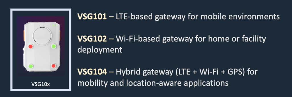
1.1.2 VSG10x – ECG Gateway
The VSG10x series acts as the central communication hub between the ECG device and the backend server.
Supported models include:
VSG101 – LTE-based gateway for mobile environments
VSG102 – Wi-Fi-based gateway for home or facility deployment
VSG104 – Hybrid gateway (LTE + Wi-Fi + GPS) for mobility and location-aware applications
Key responsibilities:
BLE connection management with VSH101
Device discovery and selection (RSSI-based)
Measurement control and session handling
Secure data transmission to backend via TCP socket
Optional location reporting (VSG104)
1.1.3 End-to-End Hardware Flow
The complete hardware data flow is as follows:
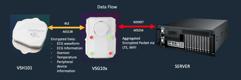
Data Transmission Layers
The system is designed with multiple layers of communication and security:
Device to Gateway (BLE)
Communication via Bluetooth Low Energy
Data is encrypted using AES128
Supports real-time physiological data streaming
Gateway to Server (TCP Socket)
Persistent socket connection
Data is aggregated and packetized
Transmission is secured using AES256 encryption
Supports both LTE and Wi-Fi connectivity
Data Content
The transmitted data may include:
ECG waveform data
ECG metadata and status information
G-sensor (motion / activity) data
Temperature data
Peripheral device information
Design Considerations
This architecture ensures:
End-to-end data security across all communication layers
Separation of concerns between sensing, transmission, and backend processing
Scalability, allowing multiple gateways and devices to operate concurrently
1.1.4 Deployment Flexibility
The hardware architecture supports a wide range of real-world deployment scenarios:
Home Monitoring – VSG102 (Wi-Fi)
Mobile Monitoring – VSG101 (LTE)
Hybrid / Location-Aware Monitoring – VSG104
Additionally, a single patient can be associated with:
Multiple gateways
Different network environments
Continuous monitoring across locations
This flexibility enables developers to build scalable and resilient ECG monitoring systems.
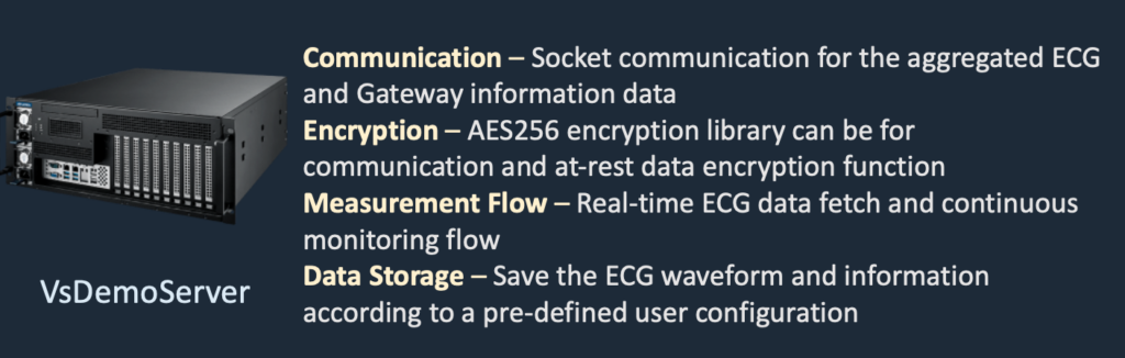
1.2 Software Architecture - VsDemoServer
The software architecture of the VitalSigns ECG system is designed to provide a real-time, secure, and extensible backend for ECG data processing.
As illustrated in the figure below, the VsDemoServer integrates four core functional components:
Communication – Socket-based data exchange between gateway and server
Encryption – AES256-based secure transmission and data protection
Measurement Flow – Continuous real-time ECG data acquisition and control
Data Storage – Configurable file-based storage for ECG waveform and metadata
This architecture provides a complete and practical foundation for developers to build their own ECG cloud platforms.
1.2.1 Quick Start
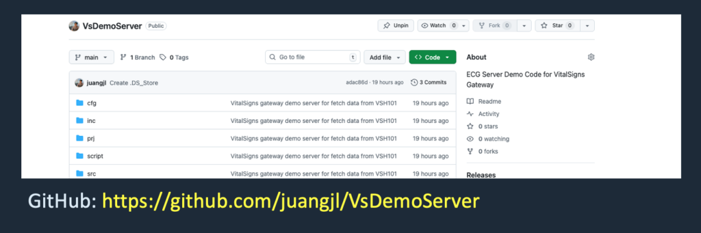
The VsDemoServer is publicly available as open-source code and can be downloaded from:
https://github.com/juangjl/VsDemoServer
This repository is actively maintained and continuously updated by VitalSigns Technology, ensuring long-term reliability and support for developers.
Step 1 – Clone the Repository
git clone https://github.com/juangjl/VsDemoServer

cd VsDemoServer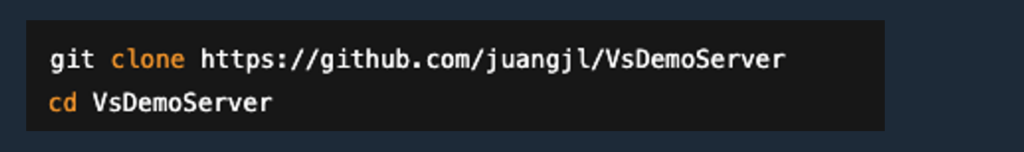
Step 2 – Build the Server
The project is implemented in C/C++ and can be built using standard Linux tools
make clean
make all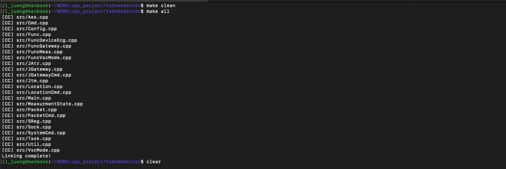
As shown in the example build output, the system compiles multiple functional modules, including:
Gateway communication
Packet processing
Measurement control
Encryption (AES)
Socket handling
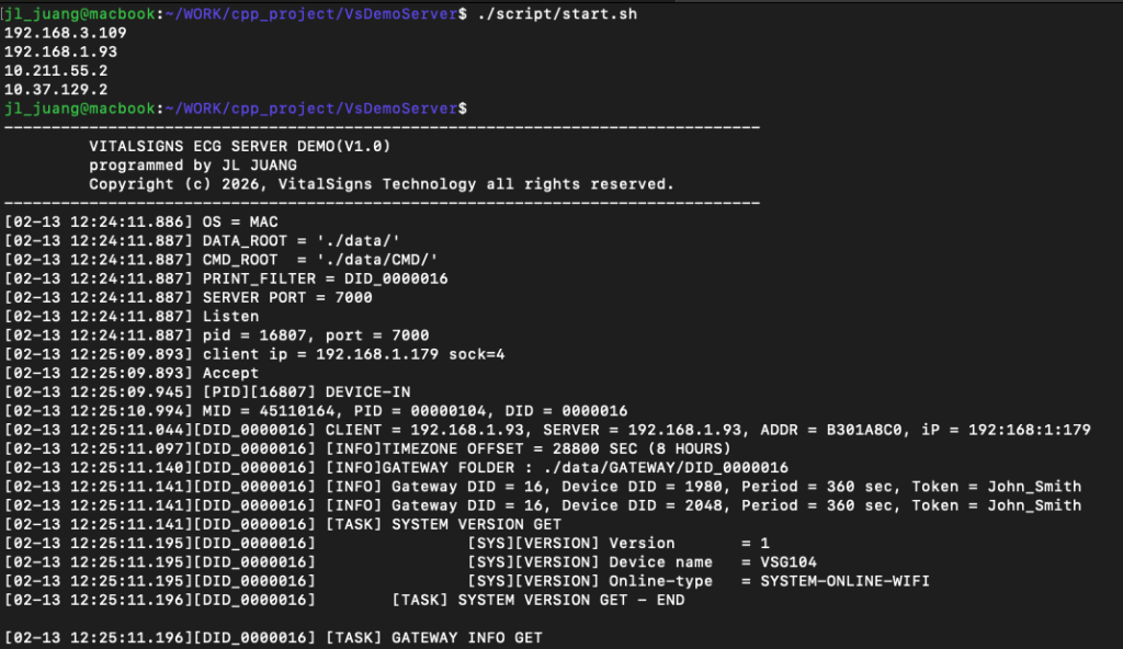
Step 3 – Start the Demo Server
After building, the server can be started using:
This will launch the VsDemoServer, which begins listening for incoming gateway connections.
Expected Result
Once the server is running:
The gateway (DID 16) will connect to the server
The ECG device (ID 1980) will be detected via BLE
The system will automatically start the measurement loop
ECG data will be received, processed, and stored in the file system
Key Advantages of the Demo Server
Open and transparent implementation
Full control over backend logic
No vendor lock-in
Easy integration with existing systems
Production-ready architecture foundation
VitalSigns provides this complete and open demo system to enable customers to rapidly build and customize their own ECG cloud platforms.
1.2.2 Backend Design Overview
The VsDemoServer is structured as a modular system composed of multiple components:
Socket Layer – Handles TCP communication with gateways
Packet Layer – Parses and constructs protocol packets
Command Layer – Executes control and query operations
Measurement Layer – Manages measurement lifecycle and state machine
Storage Layer – Organizes ECG data into file-based structures
Each gateway connection is handled independently, allowing:
Multi-gateway scalability
Process isolation
Concurrent measurement sessions
1.2.3 File-Based Architecture
Instead of relying on a database, the demo server uses a file-based storage model:
Easy to debug and inspect
No database dependency
Flexible for integration
Developers can extend this architecture by:
Replacing file storage with databases
Adding REST APIs
Integrating AI processing pipelines
1.3 End-to-Cloud Data Flow
This section describes how ECG data flows from the sensing device to the backend system, integrating both the hardware and software architectures.
As illustrated in the figure above, the system enables a secure and continuous data pipeline from the patient to the cloud backend.
1.3.1 Data Acquisition (VSH101 → Gateway)
The VSH101 ECG device continuously captures physiological signals from the patient
Data is transmitted to the gateway via Bluetooth Low Energy (BLE)
Communication is secured using AES128 encryption
The transmitted data may include:
ECG waveform
ECG status information
Motion (G-sensor) data
Temperature data
Peripheral device information
1.3.2 Data Aggregation (Gateway Processing)
The VSG10x gateway acts as an intelligent intermediary between the device and the server.
Key responsibilities:
Establish and maintain BLE connection with the ECG device
Aggregate incoming data into structured packets
Manage measurement sessions and device state
Prepare data for secure transmission to the backend
This layer abstracts device-level complexity and provides a stable interface for backend integration.
1.3.3 Data Transmission (Gateway → Server)
The gateway establishes a persistent TCP socket connection to the backend server
Data is transmitted in an aggregated packet format
Communication is secured using AES256 encryption
Supports both:
Wi-Fi connectivity (VSG102)
LTE connectivity (VSG101 / VSG104)
This ensures reliable data delivery across different deployment environments.
1.3.4 Backend Processing (VsDemoServer)
Once data reaches the backend:
The VsDemoServer receives and decrypts incoming packets
Data is parsed and processed according to the defined protocol
Measurement sessions are managed using a state-driven architecture
ECG data is stored in a structured, file-based format
1.3.5 Continuous Monitoring Flow
The system operates in a continuous monitoring loop:
Device → Gateway → Server → Storage → (Loop continues)
In this demo configuration:
360 seconds of ECG measurement
Followed by 60 seconds of rest
The cycle repeats automatically
This design supports long-term monitoring and real-time data availability.
1.3.6 Design Benefits
This end-to-cloud architecture provides:
End-to-end data security (AES128 + AES256)
Real-time data streaming capability
Separation of concerns between device, gateway, and backend
Scalability, supporting multiple gateways and devices
Flexibility, enabling integration with databases, AI models, and SaaS platforms
1.4 System Advantages and Extensibility
The VitalSigns ECG system is designed not only as a functional reference implementation, but also as a production-ready foundation for building scalable and customizable ECG cloud platforms.
1.4.1 Regulatory-Oriented Design
The system is developed based on a medical-grade design philosophy, aligned with regulatory expectations for physiological data systems.
Designed to support integration with regulated ECG devices (VSH101)
Structured data handling for traceability and reproducibility
Suitable as a foundation for systems targeting clinical or healthcare applications
1.4.2 Open and Transparent Architecture
VitalSigns provides a fully open and accessible demo backend:
Complete C-based source code is publicly available
No vendor lock-in — developers retain full control of their system
Clear and modular architecture for easy understanding and modification
This allows engineers to rapidly build and customize their own backend services.
1.4.3 Fast Deployment and Integration
The system is designed for quick setup and immediate usability:
Build and run on standard Linux (Ubuntu) environments
Minimal dependencies
Ready-to-use communication and data pipeline
Developers can move from setup to integration in a short time.
1.4.4 Flexible and Scalable Design
The architecture supports a wide range of deployment scenarios:
Multi-gateway and multi-device environments
Integration with various database systems
Extension into AI-based analytics (e.g., AF, HRV, MI)
Support for SaaS and cloud-based healthcare platforms
This flexibility enables the system to grow from a demo into a full production solution.
1.4.5 Reliable and Continuous Operation
The system is designed for long-term and stable operation:
Continuous ECG monitoring workflow (measurement + rest loop)
Independent gateway processing for improved robustness
Secure communication across all layers
These features ensure consistent performance in real-world deployments.
1.4.6 Customization and Technical Support
Every application scenario is unique.
If you have specific requirements or ideas for extending this system, VitalSigns provides professional and customized software services.
Please contact:
Our engineering team will work with you to design and implement solutions tailored to your needs, including:
Custom backend architecture
AI model integration
System optimization and scaling
Regulatory-oriented system design
2. Communication Architecture
The VitalSigns ECG system uses a custom socket-based communication architecture to enable reliable, secure, and real-time data transmission between the gateway and the backend server.
This architecture is designed with the following principles:
Persistent connection model for continuous data streaming
Packet-based protocol for structured communication
End-to-end encryption for data security
State-driven processing for measurement control
The communication flow is initiated by the gateway and maintained throughout the measurement session.
2.1 Connection Model
The system follows a gateway-initiated, persistent TCP connection model, as implemented in the socket layer.
2.1.1 Gateway-Initiated Connection
The VSG10x gateway actively connects to the backend server
The server listens for incoming connections on a configured port
Once connected, a dedicated session is established
This design simplifies deployment by:
Avoiding inbound connection requirements on the gateway
Supporting NAT and mobile network environments (LTE)
Enabling flexible cloud deployment
2.1.2 Persistent Socket Session
A long-lived TCP socket connection is maintained between gateway and server
The connection remains active during the entire measurement lifecycle
Data is continuously transmitted without reconnect overhead
This enables:
Real-time ECG data streaming
Low-latency communication
Efficient resource usage
2.1.3 Per-Gateway Processing Model
Based on the implementation in Sock.cpp, the server handles each gateway independently:
Each connection is processed in an isolated execution context
Gateway sessions do not interfere with each other
Multiple gateways can operate concurrently
This design provides:
Scalability – supports multiple devices simultaneously
Isolation – failure of one gateway does not affect others
Maintainability – easier debugging and monitoring
2.1.4 Session Lifecycle
A typical connection lifecycle is as follows:
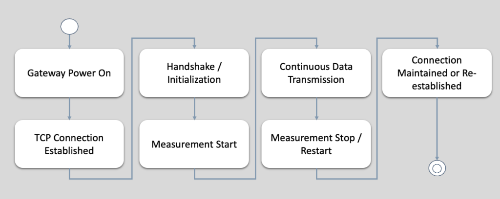
2.1.5 Reliability Considerations
The connection model is designed to handle real-world conditions:
Automatic reconnection in case of disconnection
Timeout handling for inactive sessions
Robust packet handling to ensure data integrity
These mechanisms ensure stable operation in:
Mobile environments (LTE)
Wi-Fi networks
Long-duration monitoring scenarios
2.2 Packet Protocol
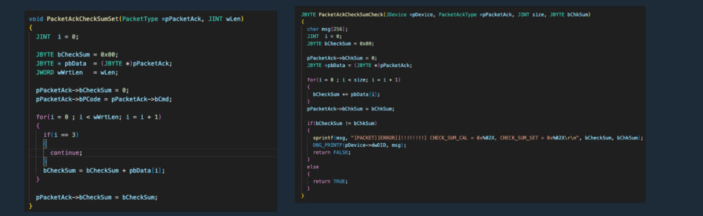
The VitalSigns ECG system uses a custom packet-based protocol to ensure structured, reliable, and secure communication between the gateway and the backend server.
This protocol is fully implemented in the open-source codebase (Packet.cpp, PacketCmd.cpp) and is designed to be transparent and easy to integrate.
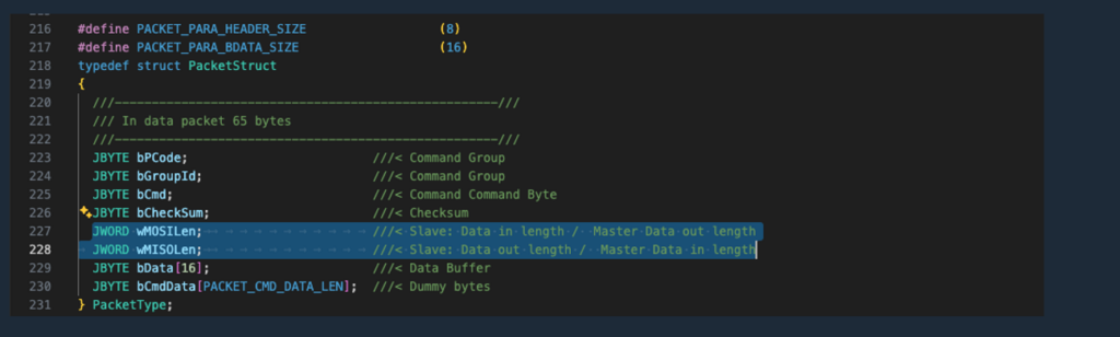
2.2.1 Structured Communication Model
All data exchanged between the gateway and server is encapsulated into well-defined packets, which include:
Command group and command ID
Payload length information
Input data (MOSI – Master Out, Slave In)
Output data (MISO – Master In, Slave Out)
Checksum for data integrity
This structure ensures that every request and response is:
Clearly defined
Consistent
Easy to parse and extend
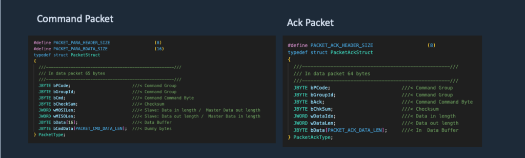
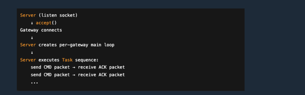
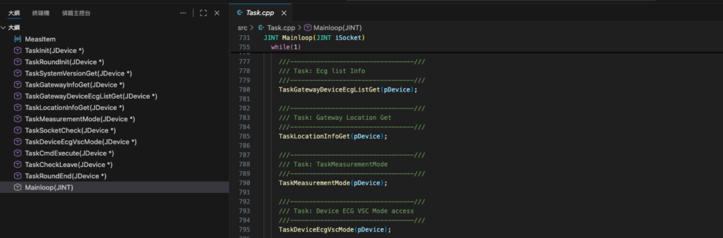
2.2.2 Server-Driven Task Loop with ACK Packets
The protocol follows a server-driven control model.
The backend server opens a listening TCP socket and waits for incoming gateway connections.
Once a gateway connects, the server creates an independent main loop for that gateway session.
Inside this per-gateway loop, the server executes a pre-defined task sequence (Task-based scheduler) and actively sends command packets to the gateway.
For each command packet, the gateway responds with an ACK packet, which contains the command result and any requested data payload.
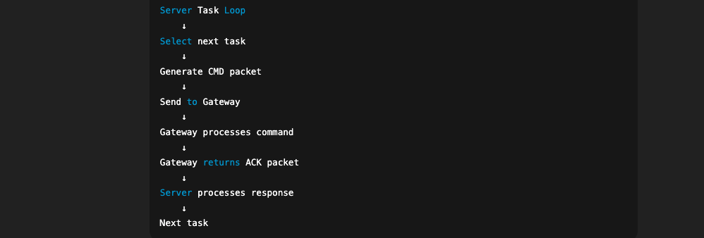
This design provides:
Deterministic behavior: the server controls when and what to query/control
Simplified integration: backend logic is centralized and easy to extend
Reliable monitoring flow: suitable for continuous measurement workflows (e.g., 360s measurement / 60s rest)
A simplified flow is shown below:
2.2.3 Command-Based Architecture
Commands are organized into groups and identifiers, enabling modular and scalable system design.
Typical command categories include:
System control (e.g., version, time, status)
Gateway management
Device (BLE) operations
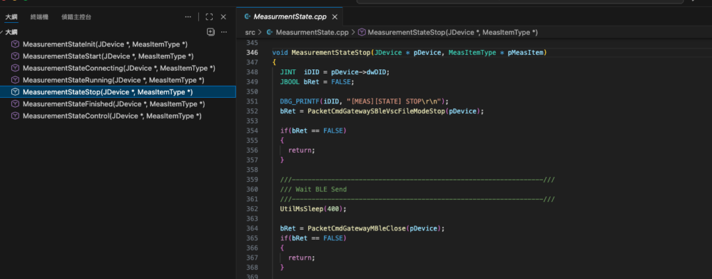
Measurement control (VSC mode)
Data retrieval and file handling
This modular approach allows developers to:
Extend functionality without breaking existing logic
Integrate new features into the same protocol framework
2.2.4 Data Integrity and Reliability
Each packet includes validation mechanisms to ensure reliable communication:
Checksum verification to detect data corruption
Defined payload sizes to prevent parsing errors
Controlled request–response flow to maintain consistency
These mechanisms ensure stable operation even in:
Unstable network conditions
Long-duration monitoring sessions
2.2.5 Open and Extensible Design
The packet protocol is intentionally designed to be:
Open – fully visible in the provided source code
Extensible – new commands can be added easily
Implementation-friendly – suitable for integration in other languages or systems
Developers can reuse or adapt this protocol to:
Build custom backend services
Integrate with existing healthcare platforms
Extend into AI-driven ECG analysis systems
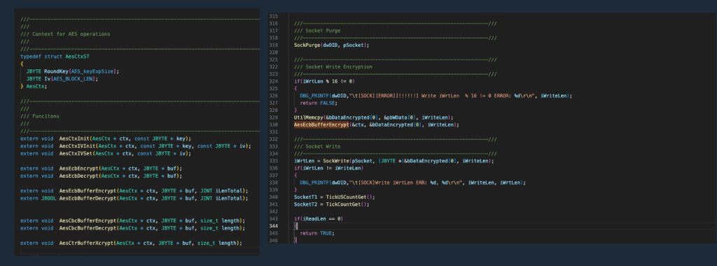
2.3 Encryption Model
The VitalSigns ECG system implements a multi-layer encryption model to ensure secure data transmission between devices, gateways, and the backend server.
The encryption mechanism is implemented in the open-source codebase (Aes.cpp) and is designed to be transparent, reliable, and easy to integrate.
2.3.1 End-to-End Encryption Layers
The system applies encryption at different communication stages:
Device to Gateway (BLE)
Data is encrypted using AES128
Ensures secure transmission over Bluetooth Low Energy
Gateway to Server (TCP Socket)
Data is encrypted using AES256
Protects data over Wi-Fi or LTE networks
This layered approach ensures that sensitive physiological data remains protected throughout the entire transmission path.
2.3.2 Packet-Level Encryption
All communication between the gateway and server is performed on encrypted packets:
Payload data is encrypted before transmission
The receiving side decrypts the packet before processing
Encryption is applied consistently across all command types
This design ensures:
Data confidentiality
Protection against unauthorized interception
Consistent handling across the protocol
2.3.3 Key Management
The encryption mechanism uses a pre-configured symmetric key shared between the gateway and the server.
Keys are initialized during system setup
Both sides use the same key for encryption and decryption
The implementation is simple and suitable for controlled environments
For production systems, developers may extend this model by:
Implementing secure key exchange mechanisms
Rotating encryption keys periodically
Integrating with external key management systems
2.3.4 Design Considerations
The encryption model is designed with the following goals:
Security – Protect ECG and patient-related data
Performance – Maintain real-time data transmission
Simplicity – Easy to understand and integrate
Extensibility – Can be enhanced for production requirements
2.3.5 Open and Verifiable Implementation
The encryption logic is fully available in the provided source code, allowing developers to:
Review and verify the implementation
Adapt the encryption mechanism if needed
Integrate with existing security frameworks
This transparency helps build trust and enables customization for different deployment scenarios.
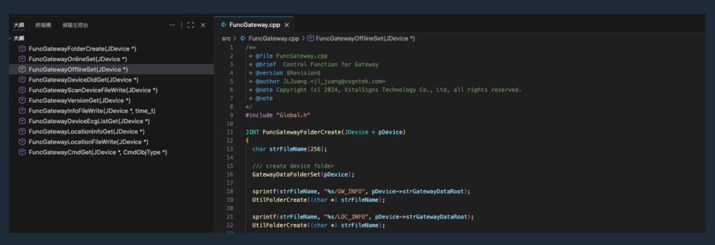
3. Command Architecture
The VitalSigns ECG system uses a command-driven architecture to control gateway behavior, manage device operations, and retrieve ECG data.
This architecture is built on top of the packet protocol and is implemented in the open-source modules such as:
PacketCmd.cppFuncGateway.cppFuncMeas.cppFuncVscMode.cpp
It provides a structured, extensible, and deterministic control mechanism for all system operations.
3.1 Command Group and Command ID
Commands in the system are organized using a two-level hierarchy:
Command Group (GROUP) – defines the category of operation
Command ID (CMD) – specifies the exact action within the group
This design enables:
Clear separation of functionalities
Scalable command extension
Easy maintenance and debugging
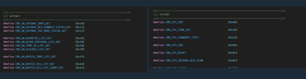
3.1.1 Command Group Categories
Typical command groups include:
System Commands
Version, time, status
Gateway Commands
Gateway configuration and control
Device (BLE) Commands
BLE open/close
Device register access
Measurement Commands (VSC Mode)
Start / stop measurement
Queue handling
Data and File Commands
File retrieval
Data access
3.1.2 Command Identification
Each command is uniquely identified by:
(GROUP, CMD)
This pair determines:
-
The function to execute
-
The expected input (MOSI)
-
The expected output (MISO)
This structure ensures that all operations are:
-
Explicit
-
Traceable
-
Consistent across the system
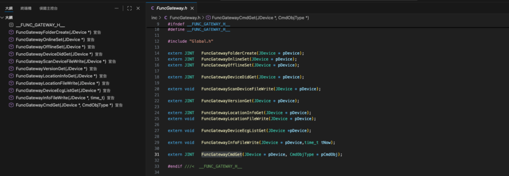
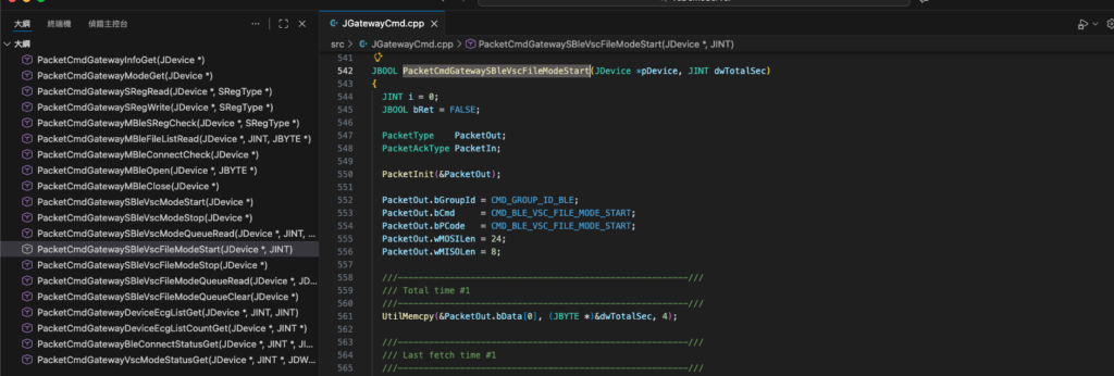
3.2 PacketCmd Design Overview
The PacketCmd layer is responsible for mapping incoming commands to their corresponding execution logic.
It acts as a bridge between:
The packet protocol layer
The functional modules (FuncXXX)
3.2.1 Command Dispatch Mechanism
When a packet is received:
The packet is parsed to extract:
GROUP
CMD
MOSI data
The system identifies the corresponding handler function
The appropriate FuncXXX module is invoked
Examples:
Gateway-related commands →
FuncGatewayMeasurement-related commands →
FuncMeasVSC mode commands →
FuncVscMode
3.2.2 Modular Function Mapping
The design separates command handling into independent modules:
Each module is responsible for a specific domain
Functions are reusable and isolated
New commands can be added without affecting existing logic
This modular approach provides:
High maintainability
Clear code structure
Easy extensibility
3.2.3 Response Generation
After command execution:
The result is packaged into a response packet (MISO)
Status and data are returned to the gateway
The gateway sends back an ACK packet to confirm execution
This ensures:
Reliable command execution
Clear feedback loop
Consistent system behavior
3.3 Command Execution Flow
The system follows a server-driven command execution model, integrated with the task loop described earlier.
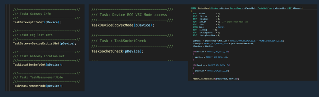
3.3.1 Task-Based Execution
Commands are not randomly triggered.
They are executed according to a predefined task sequence inside the server.
For each gateway:
A dedicated main loop is created
The server executes tasks sequentially
Each task generates one or more command packets
3.3.2 Execution Flow
A typical command execution cycle:
3.3.3 Deterministic Behavior
Because the server controls the task sequence:
The system behaves predictably
Measurement workflows are consistent
Debugging becomes straightforward
This is particularly important for:
Continuous ECG monitoring
Long-duration sessions
Regulatory-oriented systems
3.3.4 Integration with Measurement Workflow
The command execution flow is tightly integrated with:
Measurement state machine
VSC mode control
Device connection lifecycle
This ensures that:
Commands are executed in the correct order
Measurement sessions remain stable
Data integrity is preserved
3.4 Gateway Commands
Gateway commands are used to control and query the status of the VSG10x gateway.
These commands are handled primarily by the gateway function module and are responsible for managing system-level operations.
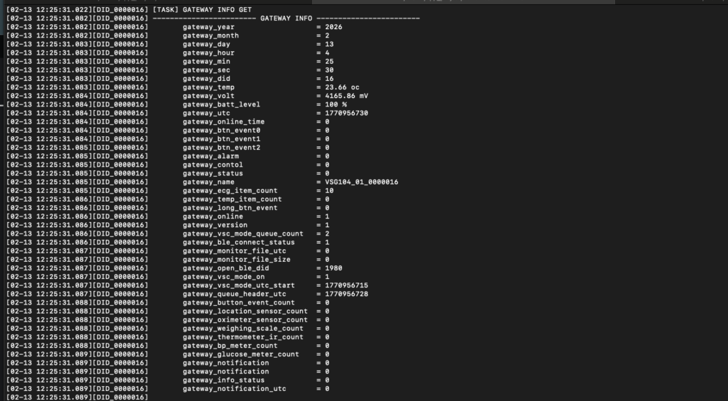
3.4.1 Gateway Information and Status
The server can request gateway-related information, including:
Device identification (DID)
System version
Network type (Wi-Fi / LTE / Offline)
Operational status
This information is essential for:
System initialization
Monitoring gateway health
Debugging and logging
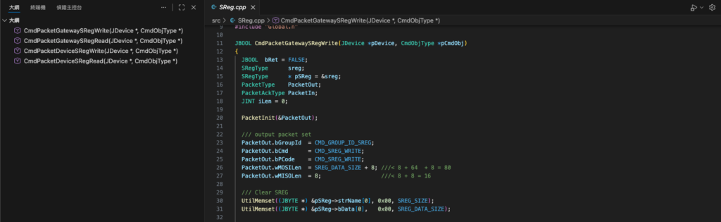
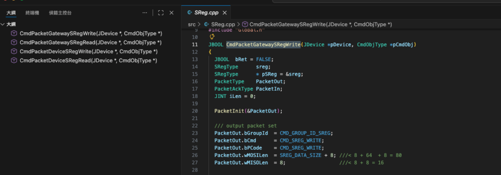
3.4.2 Gateway Configuration (SREG)
Gateway parameters can be accessed through a register-based interface (SREG):
Read gateway configuration values
Modify operational parameters
Control hardware-level behavior
Examples include:
LED control
Buzzer control
System configuration flags
3.4.3 Gateway Control Operations
The server can issue control commands to manage gateway behavior:
Set system time
Trigger system actions
Reset or reconfigure specific functions
These commands allow centralized control of distributed gateway devices.

3.5 Device (BLE) Commands
Device commands are used to control and communicate with the ECG device (VSH101) through the gateway.
These commands are handled by the device communication module.
3.5.1 BLE Connection Management
The server controls the BLE lifecycle through the gateway:
Open BLE connection
Close BLE connection
Scan and discover nearby devices
Select target device (e.g., Device ID 1980)
This ensures stable and controlled device connectivity.
3.5.2 Device Register Access (SREG)
Similar to the gateway, the ECG device (VSH101) exposes a register-based interface (SREG) that allows engineers to read and write device parameters through the gateway.
In the VsDemoServer, this interaction is designed to be simple, transparent, and file-driven, enabling rapid testing and integration.
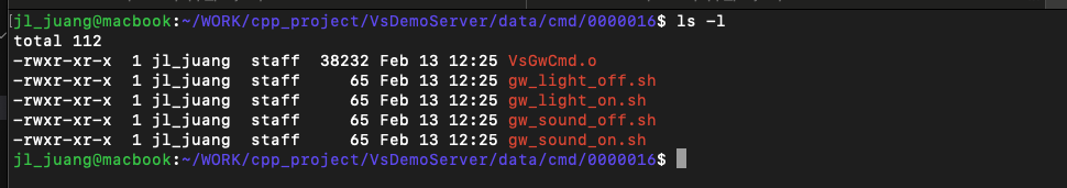
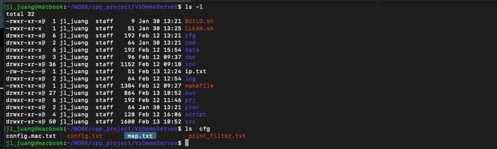
3.5.2.1 File-Based Command Mechanism
For each gateway, a dedicated command directory is created:
/data/cmd/<GATEWAY_DID>/
Example:
/data/cmd/16/
Within this directory, the system provides executable shell scripts such as:
gw_light_on.shgw_light_off.shgw_sound_on.shgw_sound_off.sh
3.5.2.2 How It Works
When the gateway is connected and online:
The user executes a shell script (e.g.,
gw_light_on.sh)The script generates a command file:
GCMD.txt
The server detects this command file
The command is converted into a packet (SREG read/write)
The packet is sent to the gateway
The gateway executes the command and returns an ACK response
3.5.2.3 Verification via GCMD.txt
The GCMD.txt file serves as a verification bridge between:
User actions
Server command processing
Gateway execution
By observing:
Command execution results
Gateway response behavior
Log output
Engineers can confirm that:
SREG read/write is functioning correctly
Communication between server and gateway is stable
The command pipeline is working end-to-end
3.5.2.4 Key Advantages
This file-based SREG interaction provides:
Simplicity – no need for complex tools or APIs
Transparency – commands are visible and traceable
Debuggability – easy to inspect and reproduce issues
Extensibility – users can create their own scripts
3.5.2.5 Developer Extension
Developers can extend this mechanism by:
Creating custom
.shscriptsGenerating custom GCMD commands
Mapping new SREG registers
Integrating with their own backend systems
This makes the system a powerful starting point for building:
Custom device control logic
Automated workflows
Full cloud integration pipelines
3.5.3 Device Data Interaction
The system can interact with device-level data:
Retrieve device status
Access measurement-related information
Manage device-level settings
These operations are essential for maintaining a reliable measurement environment.
3.6 Measurement Commands (VSC Mode)
Measurement commands control the ECG data acquisition process using the VSC (VitalSigns Cloud) mode.
These commands are implemented in the measurement-related modules.
3.6.1 Measurement Start and Stop
The server initiates and terminates ECG measurement sessions:
Start VSC mode
Stop VSC mode
This defines the active data acquisition window.
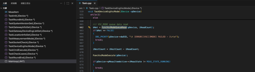
3.6.2 Queue-Based Data Handling
During measurement:
ECG data is buffered in a queue structure
The server retrieves data blocks sequentially
Data is processed and stored in real time
This design ensures:
Smooth data flow
Reduced packet loss
Efficient processing
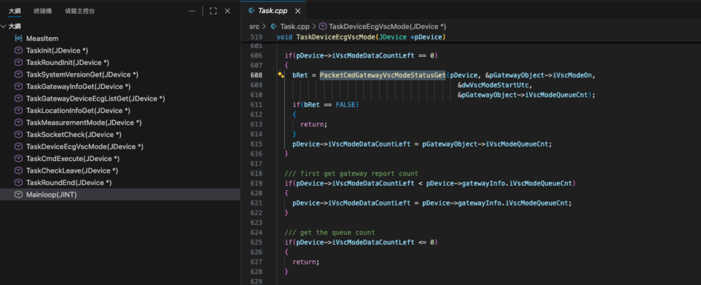
3.6.3 Measurement Status Monitoring
The server continuously monitors:
Measurement state
Data availability
Queue conditions
This allows the system to:
Detect anomalies
Maintain stable operation
Trigger recovery if needed
3.6.4 Integration with Task Loop
Measurement behavior in the system is not hardcoded.
Instead, it is fully driven by the configuration defined in map.txt, making the system flexible and easily adaptable to different deployment scenarios.
3.6.4.1 Configuration-Driven Measurement
The map.txt file defines the relationship between:
Gateway (GATEWAY_DID)
ECG device (DEVICE_DID)
Measurement duration
Rest interval
User identity
Example:
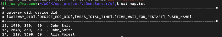
This means:
Gateway DID 16 is assigned to user John_Smith
Two ECG devices (1980 and 2048) are associated
Each device performs:
360 seconds measurement
60 seconds rest
3.6.4.2 Measurement Timing Logic
The measurement cycle is defined as:
Measurement Duration → Rest Interval → Repeat
For this example:
360 sec measurement
↓
Stop
↓
60 sec rest
↓
Restart measurement
↓
Repeat continuously
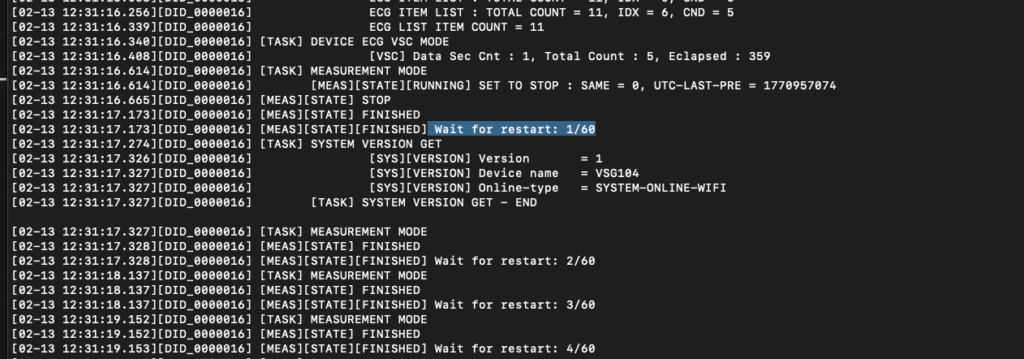
The system logs the rest countdown in real time, for example:
[MEAS][STATE][FINISHED] Wait for restart: 1/60
[MEAS][STATE][FINISHED] Wait for restart: 2/60
...
3.6.4.3 Multi-Device Handling per Gateway
A single gateway can manage multiple ECG devices.
In this example:
Gateway 16 handles:
Device 1980
Device 2048
The server processes these devices sequentially within the task loop:
Connect to device
Execute measurement
Store data
Move to next device
This enables:
Multi-patient simulation
Device redundancy
Scalable monitoring scenarios
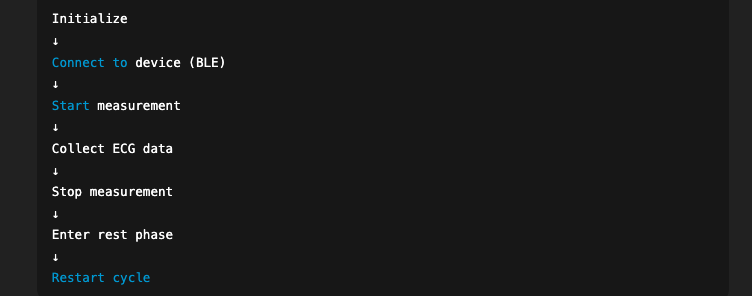
3.6.4.4 Integration with Task Loop
The server task loop reads the configuration and dynamically generates the execution flow:
Initialize gateway connection
Select device (e.g., 1980)
Start measurement (360 sec)
Stop measurement
Enter rest phase (60 sec)
Switch device or restart cycle
Repeat continuously
This design ensures:
Deterministic execution
Configurable workflow
Stable long-term operation
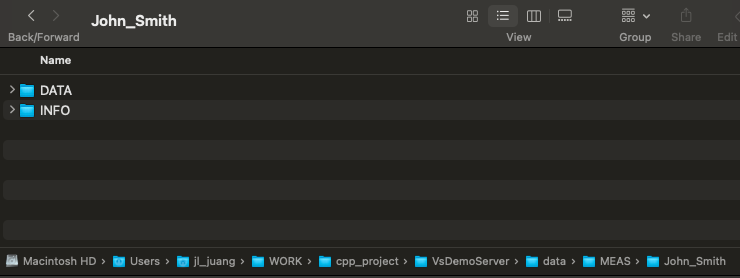
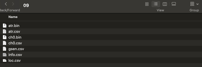
3.6.4.5 Data Storage per User
All measurement data is organized by user:
./data/MEAS/<USER_NAME>/
Example:
./data/MEAS /John_Smith/Within this directory:
DATA/→ ECG waveform dataINFO/→ metadata and session information
This structure allows:
Easy integration with database systems
Clear separation of user data
Direct compatibility with AI pipelines
3.6.4.6 Flexibility and Customization
Engineers can modify map.txt to:
Adjust measurement duration (e.g., 360 → 3600 sec)
Change rest interval
Assign multiple devices to one gateway
Simulate multi-user environments
This makes the system suitable for:
Clinical monitoring
Home healthcare
AI model data collection
Large-scale SaaS deployment
3.7 SREG Read / Write Model
The system uses a unified SREG (System Register) model to provide a consistent interface for both gateway and device control.
3.7.1 Unified Register Interface
Both gateway and device expose registers that can be:
Read (GET)
Written (SET)
This provides a standardized way to interact with system paramet
3.7.2 Advantages of the SREG Model
The register-based design offers:
Consistency – same interface across components
Flexibility – easy to extend new parameters
Simplicity – clear read/write operations
3.7.3 Example Use Cases
Typical SREG operations include:
Controlling LED or buzzer
Configuring device behavior
Reading system status
Adjusting operational parameters
3.7.4 Extensibility
Developers can extend the SREG model by:
Adding new registers
Defining new behaviors
Integrating custom hardware features
This makes the system adaptable to different applications.
4. Measurement Workflow
The VitalSigns ECG system implements a fully automated, configuration-driven measurement workflow designed for continuous monitoring and cloud integration.
This workflow is controlled by:
The server task loop
The measurement state machine
The configuration defined in
map.txt
Together, these components enable a stable and repeatable ECG data acquisition process.
4.1 Workflow Overview
The measurement process follows a continuous loop:
This loop runs continuously based on the configuration parameters.
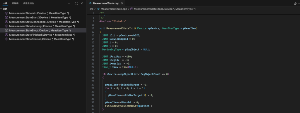
4.2 Measurement State Machine
The system internally uses a state-based execution model to control the workflow.
Typical states include:
INIT
Prepare gateway and environment
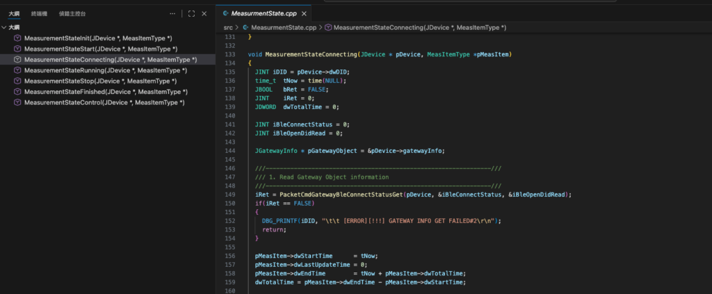
CONNECTING
Establish BLE connection to VSH101
RUNNING
Active ECG measurement
STOP
Terminate measurement session
FINISHED
Enter rest phase
4.2.1 State Transition Flow
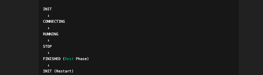
Each transition is controlled by:
Task execution
Timing conditions
Device response
4.3 Measurement Timing Control
The timing behavior is defined in map.txt.
Example:
16, 1980, 360, 60, John_Smith
This defines:
Measurement duration: 360 seconds
Rest interval: 60 seconds
4.3.1 Measurement Phase
During the RUNNING state:
ECG data is continuously streamed
Data is buffered and stored
The server monitors data availability
4.3.2 Stop Phase
After the configured duration:
Measurement is stopped
BLE communication is gracefully closed
4.3.3 Rest Phase
During the rest interval:
The system pauses measurement
A countdown is logged in real time
4.3.4 Continuous Operation
After the rest phase:
The system automatically returns to INIT
A new measurement cycle begins
This creates a continuous monitoring loop.
4.4 Multi-Device Workflow
A single gateway can manage multiple devices.
Example:
16, 1980, 360, 60, John_Smith

16, 2048, 360, 60, John_Smith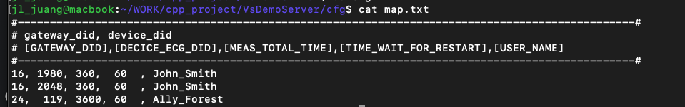
4.4.1 Device Scheduling
The server processes devices sequentially:
Connect to device 1980
Execute full measurement cycle
if 1980 goes offline, it switches to device 2048
Repeat process
4.4.2 Benefits
Supports multiple sensors per patient
Enables redundancy
Allows flexible deployment scenarios
4.5 Data Acquisition and Storage
During measurement:
ECG waveform data is captured in real time
Data is written to file system
Directory structure:
./data/MEAS/<USER_NAME>/
Example:
./data/MEAS/John_Smith/
4.5.1 Data Organization
DATA/→ ECG waveform segmentsINFO/→ metadata and session information
4.5.2 Session-Based Storage
Each measurement session is:
Time-bounded
Tokenized
Organized for easy retrieval
This structure supports:
Database ingestion
AI processing
Long-term storage
4.6 Reliability and Stability Design
The workflow is designed for long-term operation:
Deterministic task execution
Controlled state transitions
Automatic recovery through loop restart
4.6.1 Fault Tolerance
If any step fails:
The system safely exits the current state
Returns to INIT
Restarts the workflow
4.6.2 Logging and Traceability
The system provides detailed logs:
State transitions
Measurement timing
Device behavior
This enables:
Debugging
Performance analysis
Regulatory traceability
4.7 Design Advantages
The VitalSigns measurement workflow provides:
Automation – no manual intervention required
Configurability – controlled via
map.txtScalability – supports multiple devices and gateways
Reliability – deterministic execution model
4.8 Summary
The measurement workflow transforms raw ECG acquisition into a:
Continuous
Structured
Cloud-ready data pipeline
Engineers can directly build on top of this workflow to implement:
Real-time monitoring systems
AI-driven analysis platforms
SaaS healthcare solutions
5. Configuration Files
The VitalSigns Demo Server is designed to be fully configurable without modifying source code.
All system behavior — including:
Device assignment
Measurement timing
Data storage behavior
is controlled through simple configuration files located in:
5.1 Configuration Overview
The main configuration files include:
config.txt/config.mac.txtmap.txtprint_filter.txt(optional)
Each file serves a specific purpose in controlling system behavior.
5.2 config.txt / config.mac.txt
These files define the server runtime environment.
5.2.1 Key Parameters
Typical parameters include:
Server port
Defines the listening port for gateway connections
Data root path
Location for storing ECG data
Command root path
Directory for GCMD command interaction
VSC mode behavior
Controls how measurement data is saved
5.2.2 Example Usage
Users can modify these parameters to:
Change storage location
Adjust deployment environment
Configure multiple instances
5.2.3 Platform Variants
config.txt→ Linux / production environmentconfig.mac.txt→ macOS / development environment
5.3 map.txt (Core Configuration)
The map.txt file is the core of the entire system.
It defines:
Gateway-to-device mapping
Measurement timing
User identity
5.3.1 Format
<GATEWAY_DID>, <DEVICE_DID>, <MEAS_TIME>, <REST_TIME>, <USER_NAME>6. Conclusion
This tutorial has demonstrated how to build a complete ECG cloud integration workflow using VitalSigns technologies, including the VSH101 ECG device, VSG10x gateway series, and the open-source Demo Server. Through a configuration-driven architecture, engineers are able to rapidly deploy a fully functional system without modifying core source code.
From device communication and command control to automated measurement workflows and structured data output, the system provides a reliable and extensible foundation for developing healthcare applications. The use of simple configuration files, file-based command interfaces, and deterministic task loops enables fast onboarding, transparent debugging, and scalable system design.
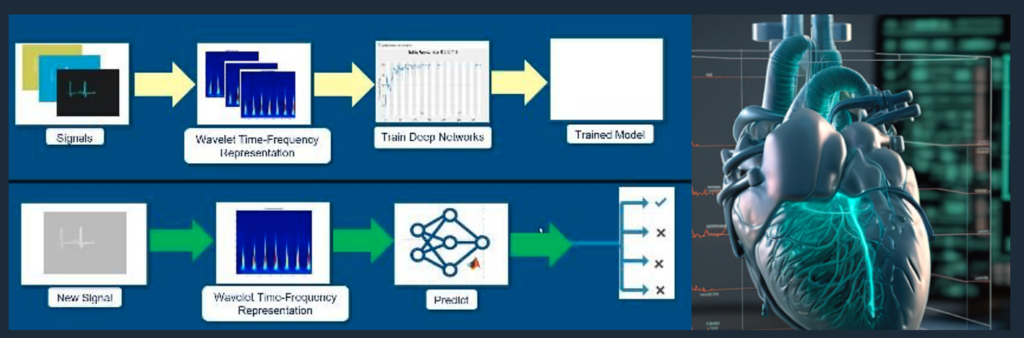
Furthermore, the data output format is designed to be directly compatible with modern cloud infrastructures and AI pipelines, supporting applications such as arrhythmia detection, HRV analysis, and predictive healthcare analytics.
VitalSigns is committed to providing an open, flexible, and compliant ecosystem for medical-grade ECG solutions. Developers are encouraged to extend this platform by integrating their own databases, analytics engines, and SaaS services.
For advanced integration or customization, please contact sales@vsigntek.com. Our team is ready to support your journey in building next-generation digital health solutions.